

Most components produced by additive technology require certain post-processing operations to produce the required surface accuracy and quality. Machining can be difficult due to complex shapes or lightweight thin-walled constructions. These characteristics lead to vibrations that have a negative impact on the entire process and, in addition to vibrations. There is a problem with aligning, aligning and clamping the prototype in the chuck or vice. In the case of the 3D metal prints this is the most important process that you need to be aware of.
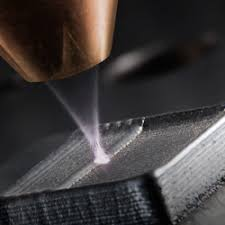
Additive manufacturing allows you to design and manufacture components that simply cannot be manufactured in any other way. This brings indisputable advantages in areas such as lightweight structures and thermal efficiency. The process itself is often fully automated and highly efficient and, moreover, everything is done with minimal waste production. However, these benefits are offset by real post-processing problems, which can be very difficult to eliminate if we choose the wrong approach.
When an additive technology component requires machining, we face a number of challenges. We must analyze and answer fundamental questions before machining.
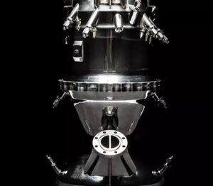
Microwave line
The case study deals with microwave conduction for telecommunication satellite. Critical factors are the weight of the line, the efficiency of microwave transmission and the size of the space. This study is a good example of the lightweight design and single component consolidation that removed the screws, resulting in efficient wave transmission and reduced kickback. By reducing the number of flanges and connecting screws, the total weight of the workpiece has been halved and the assembly process has been eliminated. These are all the benefits of additive technology, but the part still needs to machine flanges at each end of the guide.
Determination of cutting forces
A dynamometer is used to determine the cutting forces. All machining will take place in the XY plane using the process fluid. The measured data from the dynamometer show the course of the load during machining and the highest load value can be observed. This occurs when the insert enters the cutting area and is rough twice the mean load value. Furthermore, we can experiment with different depths of cut and observe their influence.
Simulation of cutting forces
So we already know the load of the cutting forces, but are the component rigid enough to withstand the load? To verify this, we perform stress analysis and apply the measured data from the dynamometer. In the meantime, we will consider establishing a classic vise behind the longitudinal part of the guide. The finite element method shows that machining around the flange edge results in significant misalignment of more than 150 microns, which will have a negative impact on the accuracy and resultant surface of the part. We, therefore, need to improve the rigidity of the part during machining. There are two options:
- Design change,
- Change clamping.
Change or optimize part design
One way to improve the rigidity of the structure is to make a minor change to the part design. As can be seen in the figure below, several handles have been added that connect both ends, thereby reducing the misalignment resulting from machining. The deflection reduction is 50%. A much more sophisticated fixture solution can be designed, but it is necessary to consider whether the fixtures do not interfere with space where there will be something else and whether we are still able to clamp the part in the vice.